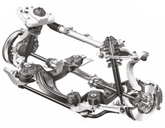
Multi-link suspensions have largely replaced conventional wishbone suspensions. The modern design offers increased driving dynamics as well as substantial added comfort. This requires a great design engineering effort. One or both wishbones are broken down into multiple components so that significantly more moving parts are installed.
How-to-guide
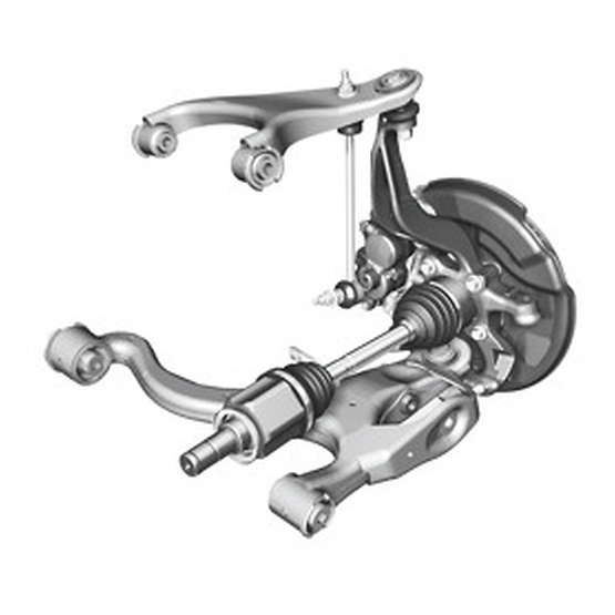
Another feature of this suspension design is that the distance between wheel centre and steering axle – the so-called disturbing force lever arm – is relatively short. This allows disturbing forces (propulsive, braking and lateral guiding forces) to be kept away from the steering as much as possible. At the same time, however, the joints move closer to the brake, which automatically exposes them to higher temperatures. This results in significantly higher requirements for the installed rubber sleeves and plastic bearing shells as well as for the grease used.
More moving parts also mean more joints connecting the parts. This results in a higher sum of moments which are divided into breakaway torque and running torque.
Fig. 1 Wishbone suspension
The breakaway torque results from the force required for setting the ball pin into motion from its resting position. To measure this moment, the ball pin is not moved for at least 24 hours before the test. The running moment results from the force required for rotating the ball pin or moving it back and forth in the joint.
The development engineers try to keep these moments as small as possible as this ensures, for example, that after cornering the front axle returns to the centre position independently and smoothly and that the suspension responds more sensitively. Today, so-called low-friction ball joints are used which have a substantially lower friction moment than previous types.
While a smoothly moving ball pin used to indicate increased wear of the ball joint, this is no longer the case today. Modern ball joints have distinctly lower breakaway torques and running torques.
Fig. 2 Multi-link suspension
The product specifications defined for a multi-link suspension are determined during extensive test procedures on a test bench as well as in the vehicle. The associated moments (running torque and breakaway torque) as well as the damping properties of a joint always have to be considered within the overall system.
The interaction with all other products must not be neglected in this context.
The influencing factors for steering systems, suspension, springs, brakes and tyres are extremely important for the functioning of the overall vehicle and for vehicle safety.
Altering individual components and specifications is only permitted with consideration of the overall concept and always requires approval from the vehicle manufacturer.
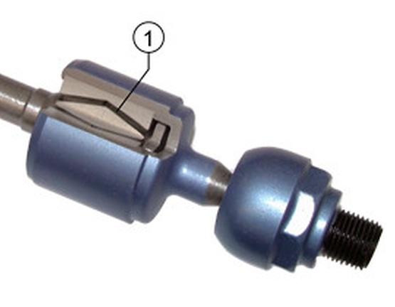
Fig. 3 Rubber matrix (1) in a joint with damping
Spare parts without vibration damping in track rod ends. Change in the diameter of the spherical heads or stabilizer links leads to increased torques.
Consequences:
- Increased wear in the rack-and-pinion steering
- Leaks in the steering
- Stiffer steering
- Return to zero position not ensured
- Damage to steering from non-absorbed impact
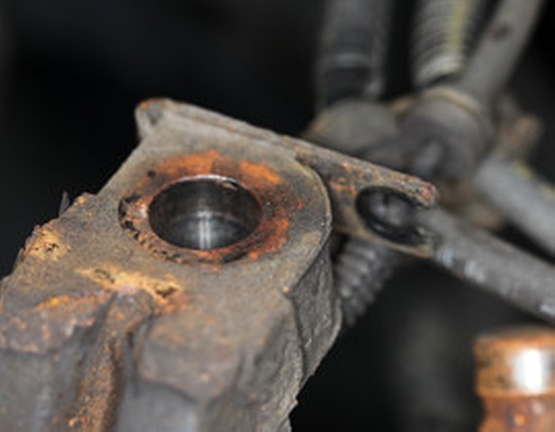
Fig. 4 Corroded eye
Mechanics should observe several points when replacing individual components.
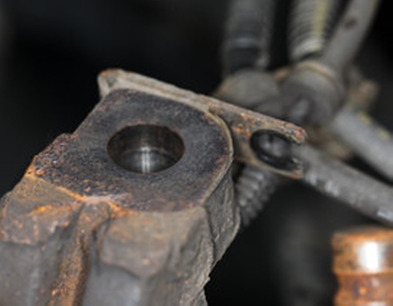
When replacing a ball joint, the eye and the rubber contact surface in which the joint is installed have to be cleaned and any rust has to be removed. The contact surface has to be free from rust as otherwise the rubber sleeve will rub against the rough surface and leak.
Dirt and moisture can enter into the joint. This leads to premature failure of the joint.
Fig. 5 Cleaned eye
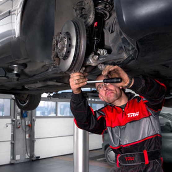
During installation, it has to be ensured that the corrosion protection layer of the circlips is not damaged, as rust causes them to lose their spring force which allows moisture ingress into the joint, significantly affecting service life.
Never tighten the ball joint with an impact wrench. There is a risk that the ball pin could start to rotate so fast that the plastic bearing shell becomes deformed by the frictional heat, leading to play in the system. Furthermore, the tightening torque can be exceeded which causes the ball pin to move too high into the eye of the stub axle. This means that the rubber sleeve can no longer fulfil its sealing function, allowing dirt and moisture to enter into the ball joint.
The rubber bearing on a control arm may only be tightened when compressed and without load to avoid twisting and therefore applying pre-tension to the bearing.
The installation errors described here can lead to premature wear or even failure of the replaced part. Garages should always carry out a wheel alignment after replacing suspension parts, even if only axle components were released. If these simple rules are followed, all suspension repair work can be carried out successfully.
Fig. 6 Always tighten ball joints manually
Nice-to-know
ZF Aftermarket product range
Discover the complete portfolio of suspension systems in our product catalog.
