The affected vehicles
VW Group vehicles belonging to the so-called B5 platform such as the Audi A4, A6, A8, VW Passat, Skoda Superb, Seat Exeo, and others are equipped with four-link suspensions. They are double-wishbone axles that, thanks to the separate link level, improve driving properties significantly. If components are replaced or even just released, the toe-in curve must also be measured and, where necessary, adjusted. The most important feature of the four-link suspension is the higher placement of the steering gear with very short tie rods. Thanks to this design, a defined bump toe-in arises when the axle compresses or rebounds. If the wheel suspension compresses on braking or rebounds on acceleration, the track changes depending on the compression or rebound path. The resulting track values are known as the toe-in curve.
If this is set correctly, the toe-in increases during rebound, i.e. when accelerating, which stabilizes the vehicle. During compression, i.e. when braking, the toe-out increases and the braking performance is supported. If the toe-in curve is set incorrectly, the vehicle breaks away during acceleration and becomes unstable. When braking, the vehicle pulls to one side despite an even braking effect.
When the toe-in curve needs to be checked
Alexander Erhart, engineering technician at ZF Aftermarket, refers to instances where the toe-in curve needs to be checked:
- If axle parts and/or the body have been damaged in an accident.
- If a complaint is made about the steering pulling when driving over bumps or during braking.
- If front-axle components such as the wheel bearing housing, steering gear, axle carrier, tie rod, guiding control arm, etc. are removed and installed or wear is present on these chassis components.
- If control arms or the tie rod are released.
How-to-guide
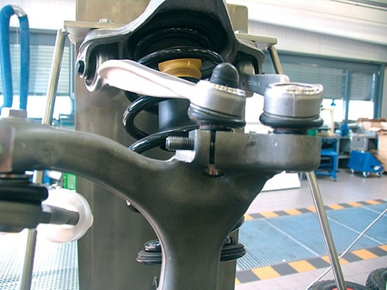
The front axle must be raised in order to check or set the toe-in curve shape. In order to do so, the V.A.G 1925 distance gage is required for the chassis and the V.A.G 1925/1 to /6 adapters are also required depending on the vehicle and hoisting platform.
Both threaded spindles are unscrewed to such an extent that they are just in contact with the front screws of the axle carrier. As a result, the vehicle may not yet be lifted. It is in the initial position (no load position B1).
The axle lift is now placed on the front jacking point and the vehicle is lifted by approximately 60 millimeters (position B2). The cylinder is subsequently driven out of the threaded spindle and it must be ensured that the retaining bolts are in the correct location and securely positioned.
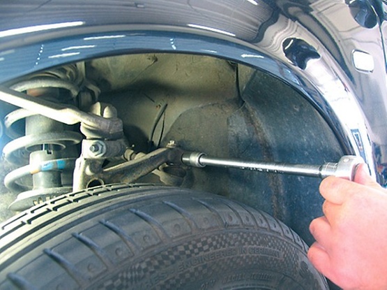
In order to perform the setting, loosen the size 16 clamping screw, screw out the adjusting screw by four millimeters, and push the tie-rod joint downwards as far as it will go. Now screw in the adjusting screw until the nominal value is reached. After tightening the clamping screw with 45 Nm, check the value once again and tighten the adjusting screw with 7 Nm.
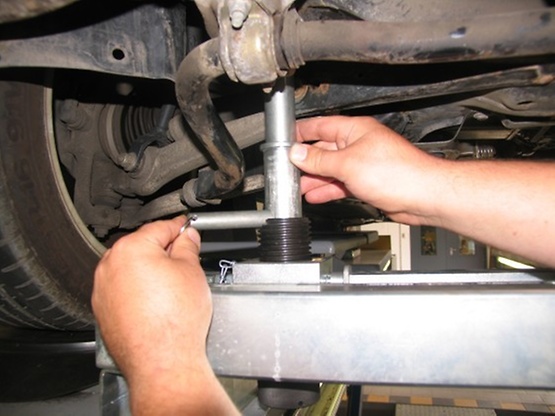
The vehicle can now be lowered once again and the threaded spindle can be wound down. The wheel alignment indicator now checks the toe-in curve once again. If the measured values during the second check are within the tolerance of the control value, the setting is OK. If the measured values are outside the control value, position B2 (+60 mm) needs to be set again.
ZF Aftermarket product range
Discover the complete portfolio of steering components in our product catalog.
